Introduction
Hi!
Hope you are well, and happy you are reading this post!
I'm, a Rep, Weronika, recently, I was trying to learn new software and managed it pretty well! So I would like to share this post and tutorial I prepared for you to get you inspired, even if you are completely new to parametric design 😊
If you would like to produce your own customised and changeable design of shelf! This post is perfect for you!
Why Grasshopper?
It is so cool, enjoyable and EASY (after you practice lots 🙂)! Also, you will get prepared for your job, because this software, Grasshopper is widely used in the industry. EVEN in Civil Engineering for instance by Ramboll Consultancy. It gives limitless possibilities for structural engineers.
Getting Started with Grasshopper
If you are new, Grasshopper is a visual programming language and environment that runs within the Rhinoceros 3D computer-aided design (CAD) application. See some basic tutorials first, I recommend:
- FoodforRhino - Dot line vs single line in Grasshopper
- FoodforRhino2 - List of Grashopper hotkeys and shortcuts
- Shortcuts - List of Grashopper icons and what they mean
- YouTube
Tutorial Overview
With this tutorial, you will create design and files ready to use by CNC Router or Laser Cutter we have in iForge!
Hopefully, soon we all be able to go back to iForge and manufacture it! Missing these days but all we can do now is to get ready, make all crazy designs for the future 😊
Step-by-Step Tutorial
Use the command Rectangular Plane from the corner-to-corner on the LHS menu.

Turn on 'Shaded' preview mode. Copy and paste using Ctrl + C and Ctrl + V, then move the new plane vertically up using the blue Gumball arrow.

Rebuild the surface using the Rebuild command.


Now, use the SoftEditSrv command to manipulate the surface.

Play with the shape of the surface to create your desired shelf design. Remember that if you change the 'Distance' option within the command, you will affect how smoothly the surface deforms.

Select both surfaces and use the DupBorder command.

Connect the corresponding border curves together using the Loft command.

Join all three surfaces (top, bottom, and the new lofted side) together now to create a single, closed polysurface.

Turn the surface vertically to imitate your shelf.

Hide the black frame. Now you can proceed to Grasshopper.


Fig 3
Connect a 'Box' component to help define the directions for dividing the solid, depending on the number of shelves you want. Then, use 'Deconstruct Brep'.

Fig 4
You can then 'List' the edges and proceed with dividing the solid as below. Use the 'slider' to set your preferred number of sections.

Fig 5: Create number of sections in the 'x' direction
'Contour': Connect your'Brep'to the 'S' (Shape) input.'List Items': Connect this to the 'V' (Vertices) of the deconstructed box, then connect its output to a'Point'component.- Set Direction: For the x-direction, use an
'x unit vector'and connect it to the 'N' (Direction) input of the Contour component. - Set Distance: Use a
'Number'and'Division'component. Connect a'Slider'to set the number of sections.

Fig. 6: Use an expression (right-click on the 'D' distance input) to ensure the sections are always inside the geometry.
-
Copy the
'Item'component and create a'Slider'. -
Find the height of the box. Use the slider until you see the green line in the preview. Leave it at that number.

Fig 7
-
Copy the three highlighted commands and connect them to your
'Item'from step 2.
-
Copy the
'Contour'commands and use them as you did in Fig 5, but this time, connect a'z unit vector'to the 'N' (Direction) input.
Next, you'll proceed with the contour sections.

Fig 8
-
To see the Rhino preview clearly, use the Hide command on the main solid. You can also right-click on components in Grasshopper and select 'Disable View'.


-
You don't need the edge sections (indicated by the blue arrows in the original tutorial) for the shelf design.

-
To delete them, use
'Cull Index'. First, use'Flatten'on the contours. This combines all contour curves into a single list so'Cull Index'can delete the 1st and last sections from the flattened list.

-
Use a
'Slider'with a value of0.0to delete the first item in the 'x' direction list. The remaining sections are shown in green.
-
Copy and paste the culling commands. Now, use
'Reverse'before'Cull Index'to delete the last section in the 'x' direction.
The 'Reverse' component makes the last item the new first item, which can then be culled with an index of 0.

-
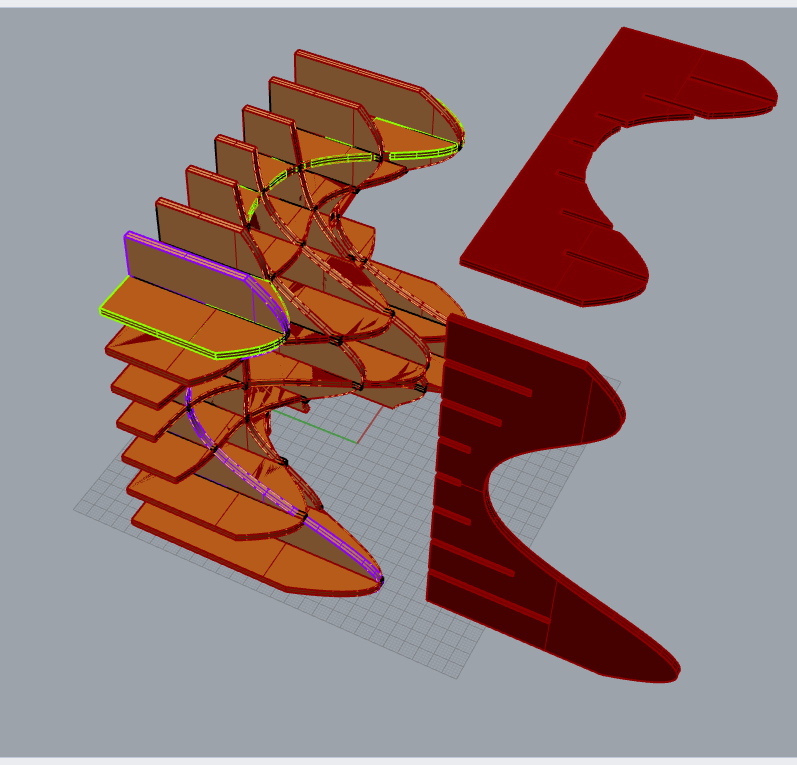
Do the same (steps 3-5) for the sections in the 'z' direction. Copy and paste the blue commands.

Flatten the data as above and get the final results:

Give the curves thickness to turn them into solids.
-
Move the curve in the x-direction.

Fig 9
-
Connect the
'Surface'(or'Boundary Surfaces') component.
-
Extrude in the 'x' direction, giving it a thickness (e.g., 2.5).

-
Copy and paste these same steps (1-3) for the 'z' direction. Remember to change the vector to 'z' and use an expression like
-x/2to ensure the extrusion is centered on the curve.
Create the slotting connections by finding the intersection between the two sets of solid curves.
-
Go to the Intersect Tool Box in Grasshopper (Intersect → Shape → Brep | Brep).

Fig 10
-
Then use
'Cross Reference'to make sure you check every single combination of intersections, as shown in example b), not a).
a) Incorrect intersection (without Cross Reference)

b) Correct intersection (with Cross Reference)

- Create boxes from the intersections, Bake them into Rhino, and then use the BoxUnion command.

Move the created boxes backwards and forwards by half their length to create the slots.
-
Use
'Deconstruct Brep'and'List Item'to find the length of the box edge. Use a'Slider'until the green line appears in the Rhino preview, then connect a'Number'parameter.Fig 11
-
Move the boxes backwards. Connect
'Move'to the 'Boxes' output. Use a'y'vector and connect a'Division'component with an expression ofx/2to move them half their length. -
Move the boxes forwards. Copy and paste the green component group.
Add an expression of
-xto the motion vector, as you want to move the boxes in the opposite direction (-y in Rhino).
Use a boolean operation to take away the intersection boxes from the solid shelf parts.
-
Use the
'Solid Difference'command.Fig 12
-
'Flatten'all the inputs for the'Solid Difference'command. Make a 'Solid Difference' between the first extrusion (a) and the set of notch solids (b):a) The first set of extruded shelf parts.

b) The set of notch boxes.
-
Copy and paste the setup and connect the second set of extruded parts and the second set of notch solids.

Here you are. That is the finished shelf!


Create the flat parts ready for a CNC machine or Laser Cutter.
-
Use Bake for both sets of final slotted curves.
-
Orientate the parts on a flat surface in Rhino.

Then, you are finished! You can extract the files in a format suitable for laser cutting or CNC.
The beauty of parametric design is that you can now go back and easily change the design.
-
Just play with the thickness sliders or the number-of-shelves sliders in Grasshopper.
-
In Rhino, go to the Standard toolbar and select 'Show Objects'. You can also type the command Show.

-
Select the original frame, and input the command CageEdit, then select
'Bounding Box'. -
Press Enter a few times to get the frame that is ready to be deformed.
-
Now just drag the points and play with the geometry, and the Grasshopper definition will update itself accordingly.

Conclusion
Hopefully, soon we will all be able to go back to the iForge and manufacture it! I'm missing these days, but all we can do now is get ready and make all the crazy designs for the future ❤️. Get in touch with questions by leaving comments below the post on the iForge website 😊.
Written by
Weronika
At
Fri Apr 24 2020